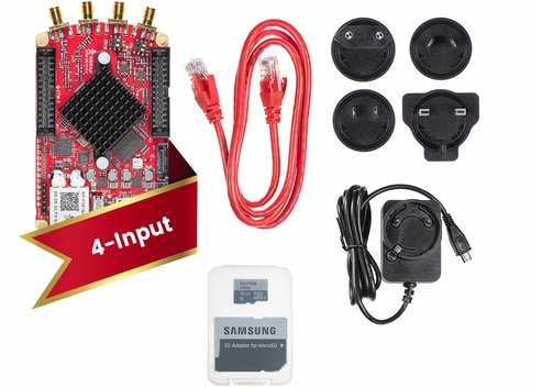
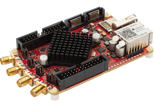
Red Pitaya STEMLab 125-14-4 input 14bit, 4-Channels
Benefits of the STEMLab 125-14-4 input SoC RF Multifunctional Signal Acquisition Platform
- Red Pitaya SoC system with four inputs at 125 MS/s, 14 bit.
- Internal/external clock selector available.
- Multifunctional and excellent performance.
Red Pitaya STEMLab 125-14-4 input 4-Channel, 14 bit
The RF signal acquisition platform Red Pitaya STEMlab 125-14-4 is a 4 inputs digitizer board, derived from the 2-channel STEMlab 125-14 unit. The STEMlab 125-14-4 features 4 input channels for enhanced performance, replacing the previous 2 inputs and 2 output channels. It also includes the Xilinx Zynq 7020 SoC.
- 4 analog input channels at 125 MS/s, 14 bit.
- Enhanced RF input performance (reduced crosstalk, noise, and distortions) compared to 2-channel STEMlab 125-14 version.
- Incorporates Zynq 7020 for increased processing capabilities and additional digital-I/O pins.
- Allows seamless switching between internal and external clocks via a jumper or control signal on the extension connector.
- Optional feature for locking internal ADC clock to an external reference clock through the extension connector (available upon customer request).
- Applications:
Automotive equipment,
multi-channel data acquisition,
base-station IF receivers,
software defined radios,
diversity receivers,
medical imaging,
communications,
non-destructive testing,
test equipment,
cellular base stations. - Can be controlled remotely using LabVIEW, MATLAB, Python, or Scilab.
- Can be reprogrammed according to the user's needs.
- An app marketplace with several free ▸apps is available.
Model Overview
| Model | STEMlab 125-14-4 input 4-channel | |
| Processor | Dual-Core ARM Cortex-A9 | |
| FPGA | Xilinx Zynq 7020 SOC | |
| RAM | 512 MB (4 Gb) | |
| System memory | Micro-SD up to 32 GB | |
| Interfaces | Ethernet 1 Gbit USB 2.0 Wi-Fi using optional Wi-Fi-Dongle |
|
| RF inputs | ||
| Channels | 4 | |
| Sample rate | 125 MS/s | |
| ADC resolution | 14 bit | |
| Full scale voltage range | ±1 V/±20 V | |
| Input coupling | DC | |
| Bandwidth | DC...60 MHz | |
| Input impedance | 1 MΩ | |
| Extension connector | ||
| Digital I/Os | 20 | |
| Analog inputs | 4 channels, 0...3.5 V, 12 bit | |
| Analog outputs | 4 channels, 0...1.8 V, 12 bit | |
| Communication interfaces | I2C, UART, SPI | |
| Available voltages | +5 V, +3.3 V, -4 V | |
| Synchronization | Trigger input through extension connector; daisy chain connection over SATA connection | |
The software apps are free. To use them with the Red Pitaya modules additional hardware options may be required, depending on the app (logic analyzer, LCR meter, VNA). Depending on the kit version they are included in the kits or available as optional accessories.
Information on product safety:
Manufacturer:
Red Pitaya, Velika pot 21, 5250 Solkan/SVN
www.redpitaya.com
Customers also bought
Last seen


