HIOKI VT1005 AC/DC High Voltage Divider
HIOKI VT1005 AC/DC High Voltage Divider
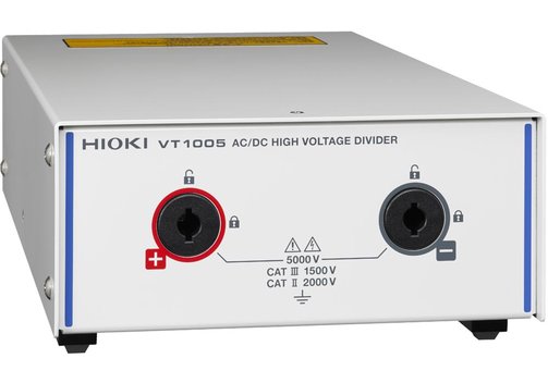
The HIOKI VT1005 is an AC/DC high voltage divider. It divides voltages of up to 5000 V (5000 VRMS, ±7100 Vpeak DC to 4 MHz) and outputs them eg. to a power analyzer such as the PW8001, PW6001 and PW3390. The voltage dividing ratio is 1000:1.
- Compact and robust AC/DC high voltage divider.
- Max. input 5000 V (±7100 Vpeak, no measurement category, anticipated transient overvoltage of 0 V), 2000 V CAT II, 1500 V CAT III.
- Measurement accuracy ±0.08% (DC), ±0.04% (50/60 Hz), ±0.17% (50 kHz).
- Frequency flatness ±0.1% amplitude band 200 kHz typ., ±0.1° phase band 500 kHz typ. (after phase correction by the power analyzer).
- Measurement Band DC to 4 MHz (-3 dB).
- Noise Resistance: CMRR 80 dB typ. (100 kHz), differential input method.
Applications of the HIOKI VT1005 AC/DC High Voltage Divide
In order to measure the efficiency of inverters with a high degree of precision, power from DC to high frequencies has to measured with high accuracy. The HIOKI VT1005 has an excellent frequency flatness for the accurate measurement at frequencies ranging from the fundamental wave to switching-frequency components. Applications are:
- Evaluation of the efficiency of Wireless Power Transfer (WPT) systems.
- Evaluation of the efficiency of inverters that use SiC power devices in industrial equipment.
- Evaluation of loss in transformers and reactors designed for use in high-voltage circuits.
- Evaluation of the efficiency of inverters that use SiC power devices in electrical railways.
- Evaluation of the efficiency of solar inverters that support high-voltage input.
Model Overview
| Model | HIOKI VT1005 | |
| Maximum rated voltage | 5000 VRMS, ±7100 Vpeak (within the frequency derating range. No measurement category: Applicable to the measurement of circuits that are not directly connected to the main power supply. Example: Measurement on the secondary-side equipment from the socket outlet of fixed installation through a transformer, etc. | |
| Maximum rated voltage line-to-ground | No measurement category: 5000 VAC/DC (±7100 Vpeak, anticipated transient overvoltage 0 V) Measurement category II: 2000 VAC/DC (anticipated transient overvoltage 12000 V) Measurement category III: 1500 VAC/DC (anticipated transient overvoltage 10000 V | |
| Voltage dividing ratio | 1000:1 | |
| Measurement accuracy | ±0.08% (DC), ±0.04% (50/60 Hz), ±0.17% (50 kHz) | |
| Frequency flatness | Band where amplitude falls within ±0.1% range: 200 kHz (typical) Band where phase falls within ±0.1° range: 500 kHz (typical; after phase correction by the power analyzer) | |
| Measurement bandwidth | DC...4 MHz (amplitude and phase accuracy specified up to 1 MHz) | |
| Common-mode voltage rejection ratio (CMRR) | 50 Hz/60 Hz: 90 dB (typ.); 100 kHz: 80 dB (typ.) | |
| Measurement method | Differential input | |
| Environmental | Operating: -10...50°C, max. 80% rel. hunmidity (non-condensing); storage: -20...60°C, max. 80% rel. humidity (non-condensing) | |
| Standards | Safety: EN 61010, EMC: EN 61326 Class A | |
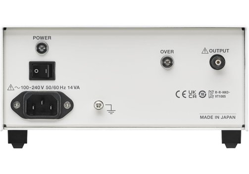
| Power supply | 100...240 VAC (50/60 Hz) | |
| Dimensions (mm) | Approx. 195 x 83 x 346; appox. 2.2 kg | |
| Measurement accuracy | ||
| Frequency | Amplitude ±(% of reading + % of full scale) | Phase |
| DC | 0.03% + 0.05% | – |
| DC < f < 30 Hz | 0.2% + 0.1% | ±0.1° |
| 30 Hz ≤ f < 45 Hz | 0.1% + 0.1% | ±0.1° |
| 45 Hz ≤ f ≤ 66 Hz | 0.02% + 0.02% | ±0.06° |
| 66 Hz < f ≤ 100 Hz | 0.1% + 0.02% | ±0.12° |
| 100 Hz < f ≤1 kHz | 0.1% + 0.02% | ±0.2° |
| 1 kHz < f ≤ 5 kHz | 0.15% + 0.02% | ±0.4° |
| 5 kHz < f ≤ 50 kHz | 0.15% + 0.02% | ±(0.08 x f kHz)° |
| 50 kHz < f ≤ 100 kHz | 0.5% + 0.02% | ±(0.08 x f kHz)° |
| 100 kHz < f ≤ 300 kHz | 1.5% + 0.5% | ±(0.08 x f kHz)° |
| 300 kHz < f ≤ 1 MHz | 5.0% + 0.5% | ±(0.08 x f kHz)° |
| Frequency band | 4 MHz (-3 dB typ.) | - |
Included: VT1005, L1050-01 voltage cord (1.6 m), L9217 connection cord (insulated BNC, 1.6 m), 9704 conversion adaptor (insulated female-BNC-to-banana plug), power cord.
Information on product safety:
Manufacturer:
HIOKI E.E. Corporation, 81 Koizumi Ueda, Nagano 386-1192/JPN
www.hioki.com
(EU branch Germany)
Related Products
Last seen


