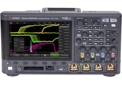
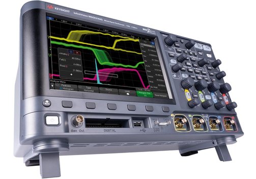
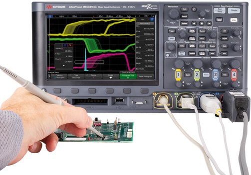
Keysight InfiniiVision DSOX3000G Series 2-/4-Channel Oscilloscope up to 1GHz
Benefits of the Keysight DSOX3000G Series Enhanced Digital Storage Oscilloscopes
- 8 additional new standard features compared to InfiniiVision DSOX3000T series.
- New waveform and measurement histograms.
- Upgradeable 16 logic channels/mixed-signal.
Keysight InfiniiVision DSOX3000G Series 2-/4-Channel Oscilloscope up to 1 GHz
DSOX 3012G, 3014G, 3022G, 3024G, 3032G 3034G, 3052G, 3054G, 3102G, 3104G
The new InfiniiVision DSOX3000G better enables capturing and isolating elusive glitches and anomalies not possible on other oscilloscopes. All models are enhanced with 8 additional standard features compared to the DSOX3000T series and include new waveform and measurement histograms that were previously only available on the InfiniiVision 6000X series. The basic scope features are 2 or 4 channels, bandwidths up to 1 GHz, sample rates up to 5 GS/s, a waveform capture rate of 1,000,000 Wfms/s and a standard segmented memory of 4 Mpts.
- Bandwidth: 100, 200, 350, 500 MHz, or 1 GHz (upgradeable to max. 1 GHz).
- 2 or 4 analog channels.
- Sample rate: Up to 5 GS/s half-channel, 2.5 GS/s all channels.
- Memory: 4 Mpts, segmented.
- Display: 8.5"/21.6 cm capacitive touch gesture-enabled display.
- Update rate: 1,000,000 Wfms/s.
- Waveform mathematics incl. FFT (windowing: Hanning, Flat Top, Rectangular, Blackman-Harris), automatic measurements, versatile trigger features.
- 16 digital/logic channels for mixed signal operation can be upgraded.
- Integrated 5 digit frequency counter (max. frequency = max. oscilloscope frequency).
- 8 additional standard features compared to DSOX3000T series:
- Waveform and measurement histograms.
- Built-in waveform generator standard.
- I2C, SPI, UART, I2S, and USB PD trigger and decode standard.
- Mask limit testing standard.
- Measurement limit testing standard.
- Frequency response analysis (Bode plots) standard.
- Enhanced HDTV video analysis standard.
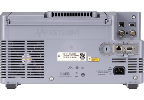
- LAN/VGA connectivity module included.
- PathWave BenchVue Software included.
Model Overview
| Model | DSOX3012G | DSOX3014G | DSOX3022G | DSOX3024G | DSOX3032G | DSOX3034G | DSOX3052G | DSOX3054G | DSOX3102G | DSOX3104G |
| Touch-screen | ✓ | ✓ | ✓ | ✓ | ✓ | |||||
| Analog channels | 2 | 4 | 2 | 4 | 2 | 4 | 2 | 4 | 2 | 4 |
| Bandwidth | 100 MHz | 200 MHz | 350 MHz | 500 MHz | 1 GHz | |||||
| Sample rate | 5 GS/s half-channel, 2.5 GS/s all channels | 5 GS/s half-channel, 2.5 GS/s all channels | 5 GS/s half-channel, 2.5 GS/s all channels | 5 GS/s half-channel, 2.5 GS/s all channels | 5 GS/s half-channel, 2.5 GS/s all channels | |||||
| Waveform update rate | 1,000,000 Wfms/s | 1,000,000 Wfms/s | 1,000,000 Wfms/s | 1,000,000 Wfms/s | 1,000,000 Wfms/s | |||||
| Memory depth | 4 Mpts, standard segmented memory | 4 Mpts, standard segmented memory | 4 Mpts, standard segmented memory | 4 Mpts, standard segmented memory | 4 Mpts, standard segmented memory | |||||
| MegaZoom | ✓ | ✓ | ✓ | ✓ | ✓ | |||||
| Zone touch trigger | ✓ | ✓ | ✓ | ✓ | ✓ | |||||
| Logic analysis (mixed-signal) | - (16 digital channels upgradeable) | - (16 digital channels upgradeable) | - (16 digital channels upgradeable) | - (16 digital channels upgradeable) | - (16 digital channels upgradeable) | |||||
| Trigger and decode | I2C, SPI, UART, I2S, and USB PD trigger and decode included | |||||||||
| Additional functions | Waveform and measurement histograms, mask limit testing, frequency response analysis (Bode plots), enhanced HDTV video analysis | |||||||||
| Signal generator | Included; standard waveforms sine (20 MHz), square/pulse (10 MHz), rampe/triangle (200 kHz), DC, noise (20 MHz), Sinc (1 MHz), exponential ries/fall (5 MHz), Cardiac (200 kHz), Gaussian pulse (5 MHz); arbitrary waveform: 1...8 kPoints, 10 bit resolution, sample-rate 100 MS/s, filter bandwidth 20 MHz; modulations: AM, FM, FSK | |||||||||
| Voltmeter | Optional: ACRMS, DC, DCRMS, frequency; resolution ACV/DCV: 3 digits, frequency: 5.5 digits; measurement rate: 100 times per s | |||||||||
| Counter | Source: Any analog or digital channel; resolution: 5 digits; max. frequency: Oscilloscope bandwidth | |||||||||
| Display | 8.5"/21.6 cm capacitive touch gesture-enabled display | 8.5"/21.6 cm capacitive touch gesture-enabled display | 8.5"/21.6 cm capacitive touch gesture-enabled display | 8.5"/21.6 cm capacitive touch gesture-enabled display | 8.5"/21.6 cm capacitive touch gesture-enabled display | |||||
| Connectivity | USB host & device, Ethernet/LAN, optional GPIB | USB host & device, Ethernet/LAN, optional GPIB | USB host & device, Ethernet/LAN, optional GPIB | USB host & device, Ethernet/LAN, optional GPIB | USB host & device, Ethernet/LAN, optional GPIB | |||||
Included: InfiniiVision oscilloscope DSOX 3012, DSOX3014, DSOX3022, DSOX3024, DSOX3032, DSOX3034, DSOX3052, DSOX3054, DSOX3102, or DSOX3104, power cord, 1 matching passive 10:1 probe per channel, standard SEC mode (secure environment), documentation CD, calibration certificate.
Note: The recommended calibration interval for these devices is 2 years. Call or send an E-Mail for more information on calibration!

Frequently Asked Questions:
Question: What does the signal capture rate mean for an oscilloscope as opposed to the sampling rate, and why is it so important?
Answer: Waveform capture rate (waveform update rate) is the speed at which a digital oscilloscope can capture complete signals. It is expressed in waveforms per second (wfms/s).
A high waveform capture rate ensures that the user gets a better insight into the signal behavior and can better detect one-off, sporadically occurring anomalies (glitchtes, jitter, etc.) and "miss" them less frequently.
The sample rate, on the other hand, describes how often a sample of the signal is taken in a given time, specified in samples per second (S/s). While the waveform capture rate indicates how fast the oscilloscope can acquire an entire signal train, the sampling rate provides information about how often a signal is sampled within a waveform cycle. It is a fundamental value in A/D conversion per se. The Nyquist-Shannon sampling theorem describes which sampling rate is required to achieve a complete "mapping" of a signal of a certain frequency. Accordingly, for a complete "reconstruction" of the signal, the sampling rate must be greater than twice the maximum possible frequency in the input signal.
How does the memory depth affect the measurement function of my oscilloscope?
Answer: The memory depth is specified in points (pts). It describes the maximum number of points a complete data set of a signal can consist of. It should be noted that the memory is usually divided between the channels (note here exactly how this is specified in the data sheet of the respective oscilloscope). Memory depth, sample rate and signal update rate depend on each other or influence each other:
Display time = Memory depth / Sample rate.
Many oscilloscopes allow a setting here to optimize the measurement depending on the signal. For example, when debugging, searching for an anomaly in a complex, digital signal stream and isolating it may require a high memory depth, while, for example, simple, stable sinusoidal signals may only require a smaller memory depth.
Agilent's Electronic Measurement Group is now Keysight Technologies.
Information on product safety:
Manufacturer:
Keysight, 1400 Fountaingrove Parkway, Santa Rosa, CA/USA
www.keysight.com
(Keysight Technologies Deutschland GmbH)
Related Products
Last seen


